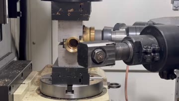
AMY CNC Brass Valve Body Rotary Machining Demo
Inspect visible rotary-fixture clamping, indexed access and tool approach around a brass valve body.
Application detail
Valve body and fitting CNC machining should be planned from the workpiece drawing, required faces, holes, threads, datum, clamping and operation sequence. AMY CNC's catalog evidence supports 8-station, 6-station and rotary-table comparison for small valve bodies and tee parts; published videos separately show brass examples. Buyers should confirm material, size, allowance, tolerance, loading, utilities and inspection before quotation.
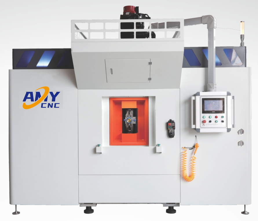
Use this page when the buyer has a valve body, fitting, connector or tee-type part and needs to organize the machining problem before choosing a machine concept. The application starts from workpiece features and operations, then connects them to the current transfer and rotary-table comparison routes.
This page does not select a final model from a part name alone. It does not establish cycle time, tolerance, output, tooling, fixture ownership or acceptance. Those items remain project decisions until drawings, process data and written scope are reviewed.
| Buyer starting condition | Process question | Published comparison route | Data still needed |
|---|---|---|---|
| A small valve body or tee-type part needs several repeated operations. | Can the required operations be organized across eight indexed stations? | Eight-station servo multi-axis transfer route | Drawing, datum, operation order, station access, clamping, loading, coolant and output context. |
| The proposed sequence may fit six stations. | Which operations belong at each station, and which tool or power-head access is required? | Six-station transfer route | Station-by-station process sheet, tool access, fixture concept, utilities and changeover needs. |
| A 1/4-inch to 1-inch valve body or tee part needs indexed upper-side access. | Would rotary positioning support the required rough machining, finish machining and tapping or threading sequence? | Servo rotary-table route | Index positions, feature orientation, datum, synchronous clamping, loading and final power-head layout. |
| The workpiece or operation sequence is not yet defined. | Which machine family should be compared before model selection? | Valve Machine Selection Matrix | Photos, drawing, material, size range, blank condition, current process and missing operations. |
The current public machine pages provide starting evidence for three relevant routes. Their catalog context supports comparison, but the buyer's drawing controls practical suitability.
| Published route | Workpiece starting point | Current public evidence | Project boundary |
|---|---|---|---|
| ATK-TV08-10HSP 8-Station Servo Multi-Axis Transfer Machine | 1/4-inch to 1-inch valve bodies and related tee-type parts. | Published 8-station configuration, hydraulic synchronous clamping, manual-loading context and product-dependent power-head layout. | Compare the shared-designation 6-station page and confirm every operation, station, tool, fixture and utility from the actual part. |
| ATK-TV08-10HSP 6-Station Transfer Machine | Small valve bodies or fittings where the proposed sequence may fit six stations. | Published six-station concept, synchronous clamping context and configurable station arrangement. | Do not assume the six-station layout fits until the process sheet and tool access are reviewed. |
| Servo Horizontal Rotary Table Valve Machine | 1/4-inch to 1-inch valve bodies and other tee parts. | Published servo rotary-table and synchronous-clamping context for rough machining, finish machining and tapping/threading; videos separately show brass examples. | Confirm indexed positions, fixture access, operation order, loading and final power-head arrangement. |
The approved videos show visible workpiece orientation, clamping, tool access and machining sequence. They do not prove model identity, cycle time, tolerance, output, certification, customer ownership or buyer-specific acceptance.
Inspect visible rotary-fixture clamping, indexed access and tool approach around a brass valve body.
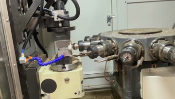
Inspect visible multi-direction tool access, clamping and successive machining steps around a valve fitting.
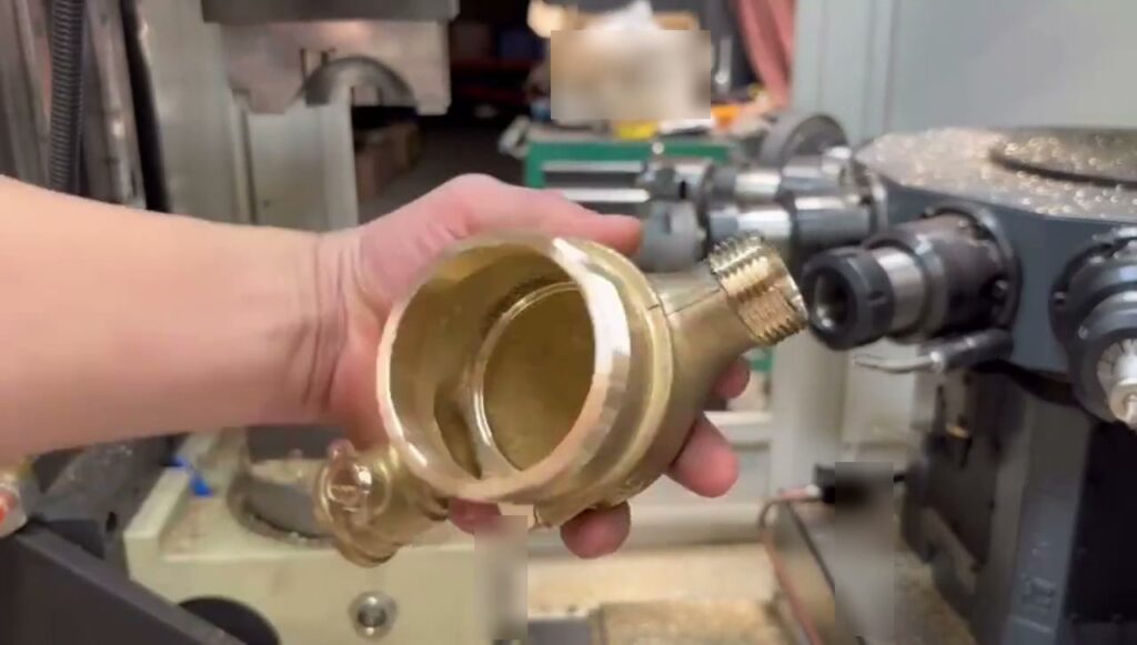
Inspect fixed workholding, repeated tool approaches around a brass multi-port body and the finished-part reveal.
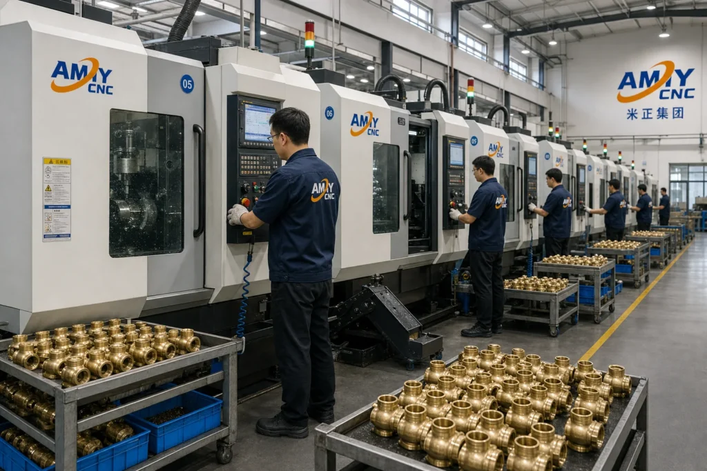
| Decision area | Public starting evidence | Confirm before quotation |
|---|---|---|
| Workpiece and material | Catalog routes identify small valve bodies and tee-type parts; published videos separately show brass valve-part examples. | Exact drawing revision, material grade, hardness or treatment, blank condition, size range and sample availability. |
| Machine concept | Eight-station transfer, six-station transfer and servo rotary-table concepts are published. | Suitable architecture, station count, index positions, axis or power-head arrangement, floor space and guarding. |
| Fixture and loading | Hydraulic or synchronous clamping and manual-loading context appears on relevant published pages. | Datum, clamping points, deformation risk, fixture ownership, manual or automated loading and changeover. |
| Machining result | Published routes support station-based comparison plus rotary-table rough machining, finish machining and tapping/threading; videos add visual process context. | Allowance, tolerances, surface requirements, burr control, tool life, coolant, cycle target and inspection method. |
| Supply and acceptance | The secure RFQ route states the buyer data and privacy workflow. | Final configuration, tooling, trials, acceptance criteria, documents, price, lead time, installation, training and warranty terms. |
| RFQ data group | What to provide | Why it matters |
|---|---|---|
| Workpiece definition | 2D or 3D drawing, clear photos, material, blank condition, size range and representative part family. | These inputs define the machining envelope, datum and first practical route. |
| Operation plan | Required faces, holes, threads, bores, milling or facing steps, allowance and proposed sequence. | The sequence controls station count, indexed access, tooling and fixture review. |
| Quality requirements | Drawing tolerances, surface requirements, critical features, inspection method and trial-part expectations. | Quality targets must be agreed before process or acceptance planning. |
| Production context | Batch size, target output context, shift pattern, loading preference, changeover frequency and available floor space. | Production context affects handling, layout and the level of automation to discuss. |
| Site and document scope | Voltage/frequency, air or hydraulic utilities, coolant preference, destination, language, packing and required documents. | Site and document requirements affect the reviewed configuration and quotation package. |
No. Valve bodies and fittings can require different datums, faces, holes, threads, fixtures and operation sequences. The drawing and process plan must control the review.
Compare transfer machining when repeated operations may be organized across indexed stations. Confirm each station and tool-access requirement from the actual workpiece.
Compare the rotary-table route when indexed access to several workpiece faces and a project-specific clamping concept are central to the process.
No. They show visible machining context only. Cycle time, output, dimensional results, finish and acceptance require separate project evidence and written confirmation.
Provide a drawing, photos, material, blank condition, required operations, datum and clamping ideas, tolerances, output context, loading, utilities and inspection method.